Preparing the tools:
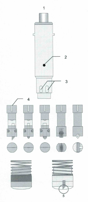
2. Secure with setscrew (1) knife holder in socket.
3. Insert knife into knife holder. Point should protrude from the knife holder approx. 5 - 10 mm.
4. Insert Allen key into holes (3) and tighten screws of knife holder.
5. Mount slipper on tool socket.
6. Adjust knife using setscrew (1) in such a way that the knife point is in the same vertical position as the slipper (5).
7. Insert tool socket into head. The red point of the tool socket must be placed on the red point of the tool reception (head).
8. Lock bayonet fixing.
Operating procedures of the Tz-P head
The knife is initialized to the cutting surface. No cutting depth must be defined. The Up position must be adapted depending on the material thickness.
Mode 2 - For entering the cut (halfcut) or for creasing the material:
The knife is initialized to the material surface. The Down Pos. (cutting depth) must be entered.
With both procedures the Offset (correction value) must be set. This value is added to/subtracted from the Down Pos./initialized depth.
The cutting depth is always entered via the menu. The setscrew of the tool soc·ket is used for securing and for the basic setting of the tool holder.
After initializing 3 tool positions are possible:
| Park Position | = | The highest possible Z-axis position is approached |
| PU (Pen Up) | = | Z zero position - set UP position |
| PD (Pen Down) | = | Z zero position+ Down pos. + Z-Offset |
Pressing the Pen key after initializing - Z-axis moves to PU position.
Pressing the Pen key again - Z-axis moves to PD position. By any additional pressing of the Pen key the position changes always between PU I PD.
By pressing the "SHIFT"* and the Pen key simultaneously the head moves into the Park position again.
Menu functions
Tz-MODUL (118)
| - UP POS | 1181 | Distance of knife to Z zero position in the Pen Up mode |
| - DOWN POS | 1182 | Tool depth based on the Z zero position in the Pen Down mode |
| - OFFSET | 1183 | Correction value added/subtracted to the Z zero position/cutting depth |
| - Z-INIT | 1184 | Initialization process is started |
| - Z-INIT AUTO | 1185 | without function |
| - Z-LOWER | 1186 | Lowering speed of Z axis |
| - Z-LIFT | 1187 | Lifting speed of Z axis |
| - MODE | 1188 | without function |
| - PRESSURE | 1189 | without function |
* SHIFT is the center "moving key" - refer to User's Manual, chapter 2-20
Initializing Z-axis:
- Tool socket is inserted into head and locked.
- Trigger function Z-INIT (1183). By pressing the moving keys (x-direction) the Z-axis is moved up / down until the slipper / knife is touching the material surface / cutting surface. By pressing the "SHIFT" key simulataneously the lowering/lifting speed is increased.
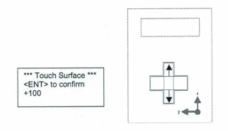
- When surface is reached confirm with <ENT>.
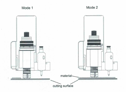
Settings for cutting in mode 1
(Z-zero point = cutting surface)
Settings for cutting in mode 2
(Z-zero point = material surface)
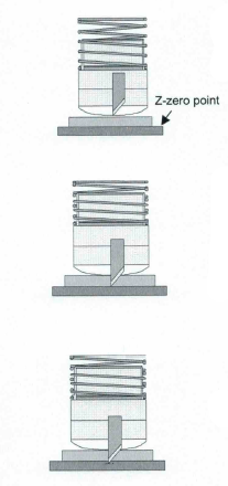
Pen up position = Z-zero position - Up position
In the Pen Up mode the knife is moving over the material in the preset height.
Up Pos. = material thickness + 2 mm
"Diecut"
Pen Down position = Z-zero point
The knife is in a down position as thick as the material or down to the upper edge of the cutting surface. In order to get a good cutting quality the knife, however, must cut into the cutting surface. This cutting depth depends on material and is adjusted with the Z-Offset (1183).
Cutting depth = Z-zero point + Offset
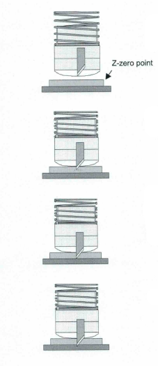
Pen up position = Z-zero point - Up position
In the Pen Up mode the knife is moving over the material in the preset height.
"Half cut"
Pen Down position = Z-zero point + Down position
"Diecut"
Pen Down position - Z-zero position + material thickness
The knife is in a down position as thick as the material. In order to get a good cutting quality the knife, however, must cut into the cutting surface. This cutting depth depends on material and is adjusted with the Z-Offset (1183).
Cutting depth = Z-zero point + Down Pas + Offset

The plotting pen
Inserting the pen:
- Select pen no. <ESC> 2
- Loosen clamp screw (Fig. 1 /1) and insert pen.
- Lower pen (Pen key)
- Push pen down by hand about 0.5 mm and tighten clamp screw.
The contact pressure of the pen is set with the adjusting screw. It should be set to approx. 100 grams. This is obtained when the distance between tool socket and setscrew is 7 mm.

A totally screwed in adjusting screw generates a contact pressure of about 300 grams. This value would be too high and would in some cases impede the lowering of the pen.
Pen delays:
The pen delays have a direct influence on the lowering response of the pen and should be adapted depending on the tool used (e.g. ink pen).
If delays are=> 30 ms then the pen is lowered more slowly.
Setting of delays is carried out via menu <ESC> 1142.
| Ball point | Ink pen | |||
| Tool Delay | Tool delay | |||
| 1 Before Down | 0 | 1 Before Down | 0 | |
| 2 After Down | 20 | 2 After Down | 50 | |
| 3 Before Up | 0 | 3 Before Up | 0 | |
| 4 After Up | 20 | 4 After Up | 50 |
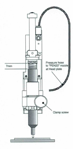
Pen-20 Module (P20)
General
The Pen-20 modul is used as the stardard Pen Module, it has altough a stroke of 20mm.
Pen inserts of? 15 and 20mm can be used.
Air pressure
The Pen-20 module is pneumatically operated. The pressure hose to the P20 module comes from the nozzle on the head plate (labelled 'PEN 20')
The Pen-20 module operates with 6bar (black hose with a white stripe from the maintenance unit).
The pen
The spring force of the cartridge is adjusted with the adjustment knob at the pen insert. It should be approximately ~7mm out of the insert sleeve. The given pressure is then about 1OOg.
Inserting the pen
- Select Pen 2 2112
- Lower the pen holder with PEN-key
- Loosen the clamp screw.
- Insert the pen into the pen module and slide it down on to the material, then press it ~1 mm further down (the cartridge is pushed into the pen sleeve).
-Tighten the clamp screw.
-Lift the pen holder with PEN-key.
Pen Wait-times
The wait times have a direct influence to the down caracteristics of the Pen and thus to the plotting line.
Example:
| BEFORE DOWN | 0 | 1141 U | |
| AFTER DOWN | 80 | 1142 U | |
| BEFORE UP | 0 | 1143 U | |
| AFTER UP | 50 | 1144 U |
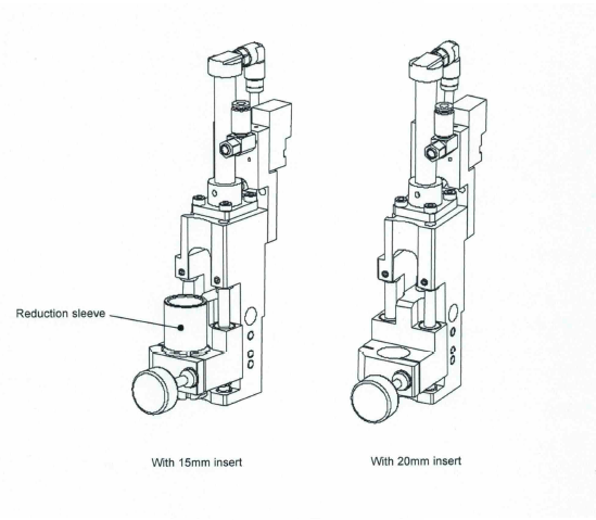
Using? 15 and 20mm Pen insert
Remove the reduction sleeve when using? 20mm
Pen insert.
